Raspberry PID: Building a Real-Time Metro Arrival Board with Raspberry Pi and LEDs
by John B. Hall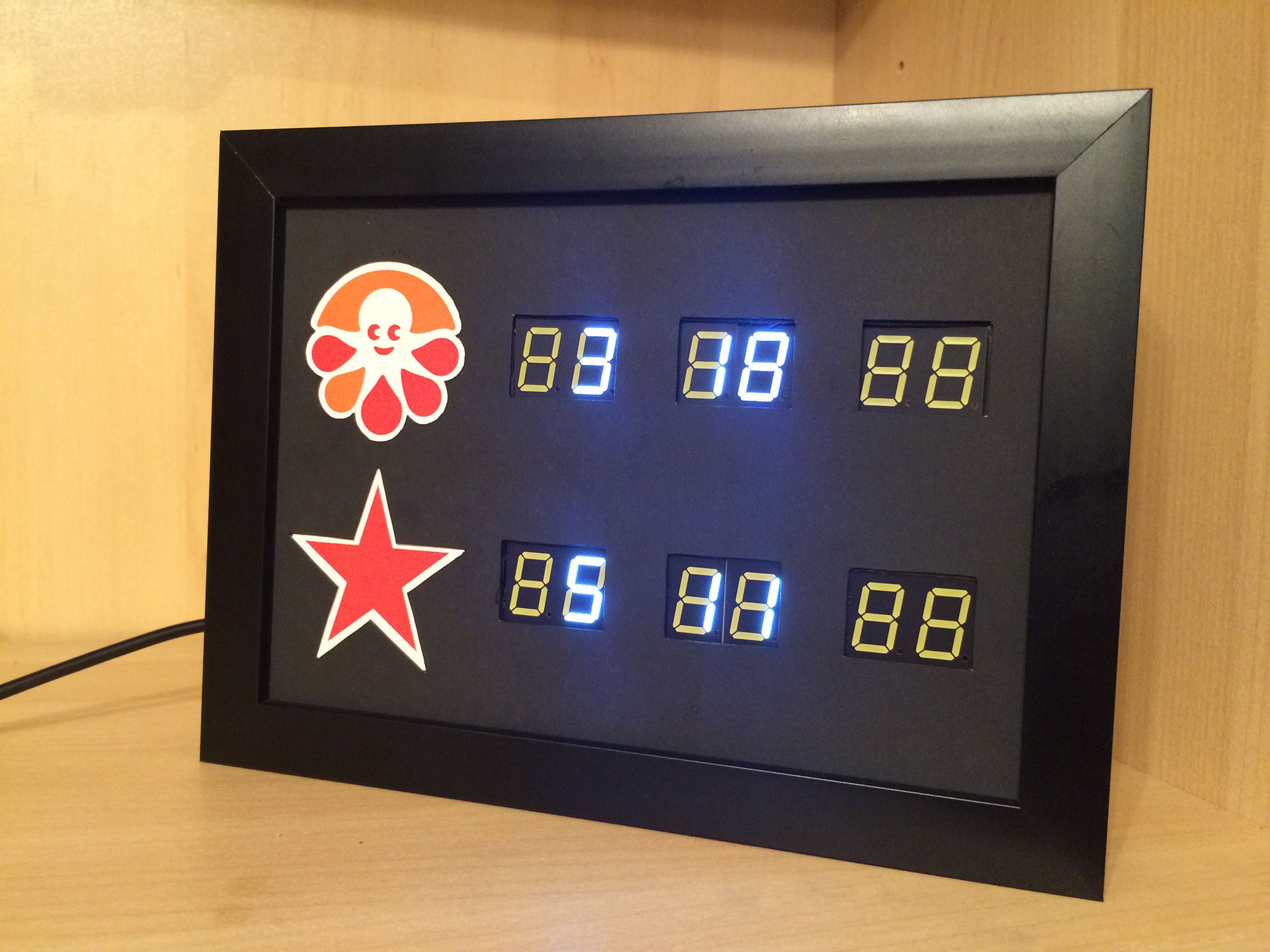
When I'm leaving my apartment to ride the Metro, I often wish I could quickly know whether there's an incoming train worth hurrying to catch. I could pull up one of the DC Metro apps and look up my stop, but that process is annoying. To give myself at-a-glance access to train arrival predictions for Ballston station, I built a real-time PID (Passenger Information Display) for my apartment using a Raspberry Pi and 7-segment LEDs. I call it "Raspberry PID," and here's how I made it.
Set Up Raspberry Pi
I used a Raspberry Pi 2 Model B running NOOBS/Raspian.
Solder LED Displays to their I2C Backpacks
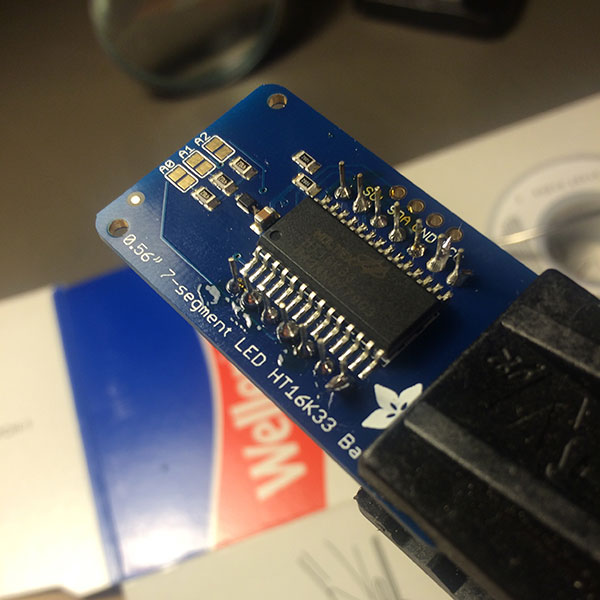
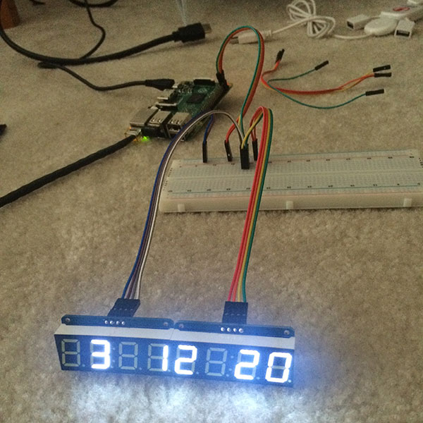
The 4-digit 7-segment LEDs from Adafruit come with an I2C backpack that is easy to interface with from the Pi. I first soldered the displays to the backpacks, and then I soldered the address-adjust pins. I used 4 displays, and by soldering the address jumpers I was able to identify each backpack uniquely (0x70, 0x71, 0x72, 0x73) so they could all run off a single I2C bus. This was my first time soldering, so a #SolderSelfie was obligatory.
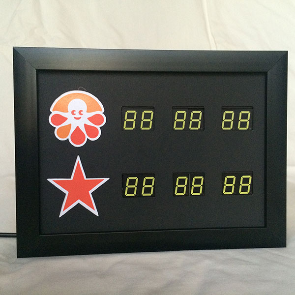
Design the Layout
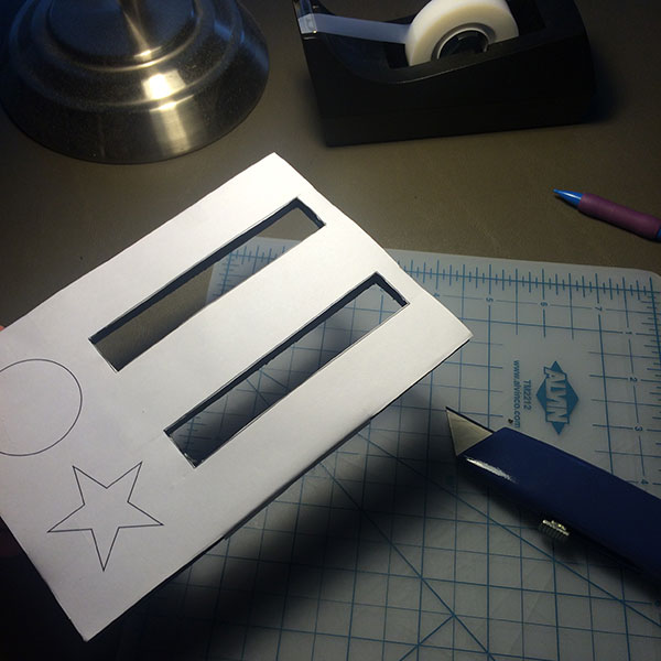
The layout I designed is specifically tailored to my uses. The first row is for westbound Orange trains going to CustomInk, where I work, labeled with our octopus mascot Inky. The second row is for Orange and Silver trains traveling downtown. Printed copies of the Illustrator file were perfect guides for precise cuts.

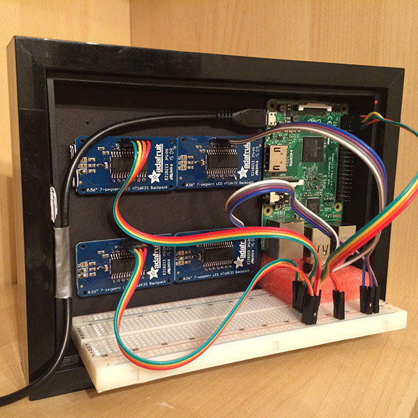
Connect LED Displays to Pi via Breadboard
Currently, I have the displays connected to Pi through a regular breadboard, but I will eventually solder everything in place using a perma-proto breadboard.
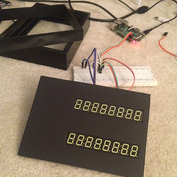
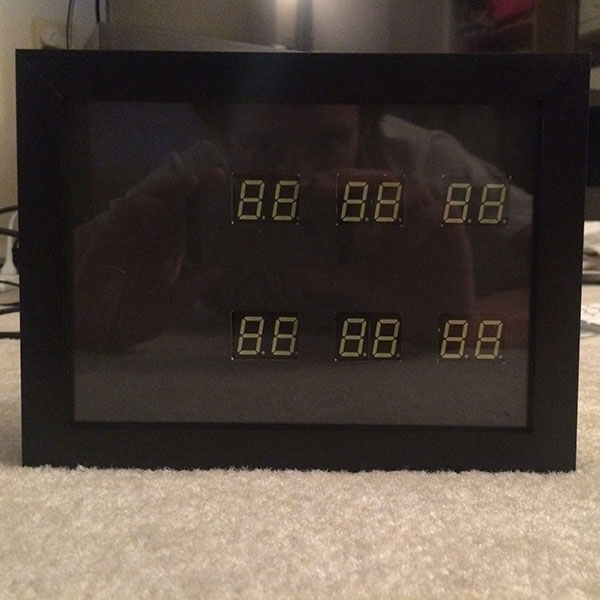
Assemble the Frame
This 5x7 deep-box frame from Target was perfect for this project. The LED displays fit snugly into the gaps of the foam board, and in front of that, a black mat masks the digits that aren't in use (the 3rd and 6th of each row). Right now all my wires hang out the back, but I plan to get everything self-contained within the frame boundaries so that only the power cord sticks out through a small hole in the frame backing.
Code!
The train data comes from WMATA's Rail Prediction API and the Pi connects to the Internet through a mini WiFi adapter (USB). On top of Adafruit's Python library for Raspberry Pi, I wrote a script that retrieves train data every 20 seconds, filters and formats it, and then prints it out to the LEDs. I modified the Pi's /etc/rc.local file to run the script on load, so the board fires up whenever the Pi is turned on.
That's it! Never again will I wolf down my cereal and sprint to the train, only to have to wait ten minutes on the platform.
Supplies and Cost
For the actual device
| Raspberry Pi | $45 |
| 4 7-Segment Displays | $44 |
| MicroSD Card | $13 |
| WiFi Adapter | $12 |
| Power Cord | $12 |
| Picture Frame | $12 |
| Breadboard | $6 |
| Foam Board | $3 |
| Total | $147 |
Equipment that I can use again for future projects
| Soldering Station | $38 |
| Wires | $14 |
| Solder | $9 |
| Diagonal Cutters | $7 |
| Pliers | $3 |
| Total | $71 |
I presented this project at the Transportation Techies Meetup group in Arlington, VA on June 18, 2015. Slides here.